Reactive power: an unnecessary burden and cost
with a negative effect on electrical installation efficienc
Today, reactive power is present in many installations. It creates an extra load on the installation, equipment and transport infrastructure (such as cables and pipes). Reactive power can arise in the external network and in the local network, and may be caused by the energy supplier as well as the end user. It has a negative effect on efficiency and capacity and introduces unnecessary (energy) losses and costs. The solution: installing a Cos Phi capacitor bank and/or a Passive or Active Harmonic Filter.
Excessive reactive power can lead to
Active power versus reactive power
Electrical energy in an electrical load is partially converted to other forms of energy. In an electrical motor this could be mechanical energy, but also heat. All energy converted from its electrical form to any other kind of energy in a certain time period is called active power (kW).
However, electrical energy may also be transported towards the load but not converted into another form of energy. This energy, transported over a certain time period, is called reactive power (kVAr). Reactive energy will be transported back to the source. This extra transport of energy results in additional energy losses in cables and requires additional capacity from the electrical installation and cables.
The next logical question would be: why is this energy transported but not converted? We can distinguish three types of electrical load: linear, capacitive and inductive. A linear load will completely convert all energy delivered to the load: this would have 100% active power and 0% reactive power.
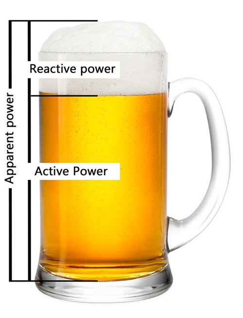
A proportion of a volume of electric power is always used effectively. This is called the active power or actual power (kW). In an installation, actual power is converted into mechanical energy (motor), light (lamp) or thermal energy (heating or cooling). However, part of the power is always lost. This is called the reactive power (kVAr). This power is required for the generation of magnetic and electric fields, necessary for the proper functioning of devices such as transformers, control gear and gas discharge lamps. The total power, or apparent power, is the sum of actual (active) power and reactive power.
As a result of reactive power, the apparent power increases, as does the load and the minimum required capacity of the electrical infrastructure. Greater connected capacity is required, along with more (powerful) transformers, thicker cables, more copper and so on. Reactive power also leads to a higher energy bill, due to higher energy losses within the installation. In addition, energy suppliers are increasingly charging the costs for the included reactive power to the end user. This ‘fine’ can be found on the electricity bill.
Total power (kVA) = actual (active) power (kW) + reactive power (kVAr)
The picture above compares power to a full glass of beer (the total or apparent power). The liquid (which you drink) represents the actual power and the foam (the extra product) represents the reactive power.
Interested in the possibilities?
We are happy to help you gain insight into the quality of electrical energy within your installation. By means of measurements, analysis and appropriate reporting, we offer you insight into the Power Quality status of your installation.
In which situations is there NO reactive power?
With an ohmic/resistive load, available power in the installation is directly converted into usable energy. Examples include electric ovens, light bulbs and radiators. The current in this case is in phase with the voltage.
In which situations there is reactive power?
To a greater or lesser extent, reactive power is present In each electrical installation. This presence is closely related to the ever-increasing use of electronics and inductive loads.
We can distinguish the following types of reactive power
- Shifting reactive power: caused by inductive and/or capacitive loads. These ensure current ‘lags/runs late’ behind the voltage (inductive) or that the current ‘leads/runs ahead’ of the voltage (capacitive).
- Distortive reactive power: this is the ‘unwanted’ part of the apparent power associated with harmonic pollution caused by non-linear loads.
A combination of these types may also occur. Certain loads such as UPS systems, cause both inductive and distortive reactive power. Specialist knowledge is required to find the right solution, or combination of solutions. HyTEPS has the knowledge, experience and high-quality products to support this.
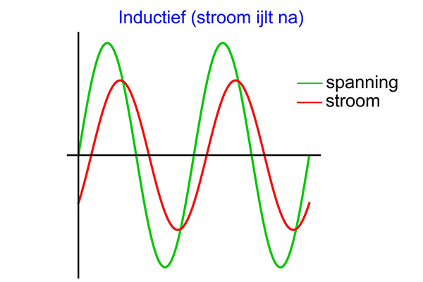
Inductive
reactive power
- Arises as a result of inductive loads.
- Occurs especially in installations with many inductive loads (including transformers and welding equipment).
- For example: industrial installations.
- The current and voltage are not in phase; the current ‘lags/runs late’ behind the voltage.
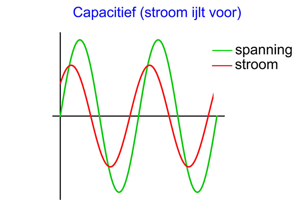
Capacitive
reactive power
- Arises due to capacitive loads.
- Occurs especially in installations with a high proportion of electronics. Also found in installations with oversized capacitors.
- For example: data centers, hospitals, tunnels.
- The current and voltage are not in phase; the current ‘leads/runs ahead’ on the voltage.
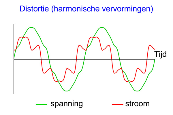
Distortive
reactive power
- Arises as a result of harmonic components in the electrical installation.
- Occurs especially in installations with (many) non-linear loads (rectifiers, frequency converters, UPS).
Also found in low-voltage installations. - Harmonic currents cause deformations of the current, causing voltage distortion.
Reactive power is related to the power factor
The power factor is the ratio between the actual (active) power and the apparent (total) power in an alternating voltage installation. In an ideal situation, the power factor equals 1. Voltage and current are in phase; the active power in this case is equal to the apparent power. Due to the presence of inductive and/or capacitive reactive power the apparent power increases and the power factor becomes less than 1.
The power factor is a combination of the power factor (cos φ) and the total harmonic pollution (THD, or Total Harmonic Distortion). Harmonics occur in installations with non-linear loads. This distorts the sinusoidal shape of the current. The total of all harmonic currents can cause voltage distortion.
With a decreasing power factor, an increasingly large current is needed to deliver the same actual power at the same voltage. A power factor that is too low may result in an unnecessary load to the grid, additional losses in the transport cable, and dangerous situations.
Solutions for reducing reactive power
A Cos Phi compensation bank or capacitor bank can be used to compensate for the inductive reactive power and optimize the power factor. The Cos Phi capacitor bank provides the power required for inductive loads. No reactive power is drawn from the grid anymore. The current no longer runs late on the voltage; voltage and current are in phase. Avoiding fines for reactive power helps earn back the investment on a capacitor bank within 1-2 years.

‘t Voske avoids unnecessary losses and increases capacity

Sappi reduces losses by installing capacitor banks

No more reactive power penalty for Fouragehandel Verhoeven

VDL increases operating efficiency and avoids unnecessary losses

Haval saves electricity and extends lifespan of equipment

Xella takes steps toward sustainability

Van Munster Recyclers increases energy efficiency and reduces costs

Naber can make optimal use of power by Cos Phi improvement

More power and lower costs, emissions and grid load at SNB